Multilayer ceramic capacitors (MLCCs) are generally the capacitor of choice for applications where small-value capacitances are needed. They are used as bypass capacitors, in op-amp circuits, filters, and more.
Advantages of MLCC include:
Small parasitic inductance gives better high-frequency performance compared to aluminum electrolytic capacitors.
Better stability over temperature, depending on the temperature coefficient.
Disadvantages
Small capacitance per volume, especially for class 1 dielectric materials (NO/COG).
DC bias instability.
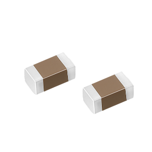
Construction
MLCCs are made of alternating layers of metallic electrodes and dielectric ceramics.
Temperature Coefficient
Class 1 ceramic materials (e.g., NPO, COG) have very low-temperature coefficients, meaning that their capacitance varies very little over temperature. They also have low dielectric constants, meaning that capacitors built with class 1 materials have very small capacitance per volume. NPO and COG are very common class 1 temperature coefficients and have a temperate coefficient of 0 and tolerance of +/-30 ppm.
Class 2 (X,Y,Z) ceramic materials are less stable over temperature but have a higher dielectric constant, which means that capacitors with more capacitance are available in the same volume. X7R is a very common class 2 temperature coefficient, and X7R capacitors typically have tolerance of 5%, 10%, and 20%.
Examples include:
ㆍX7R is rated to operate from -55 C to +125 C, with +/-15% change in capacitance over the temperature range.
ㆍX5R is rated to operate from -55 C to +85 C, with +/-15% change in capacitance over the temperature range.
ㆍY5V is rated to operate from -30 C to +85 C, with +22/-82% change in capacitance over the temperature range.
Capacitors with wider temperature ranges and more stable temperature characteristics tend to cost more.
Voltage Rating
The voltage rating indicates the maximum safe voltage that can be applied across the capacitor. In practice, designers should use a capacitor with a voltage rating that is higher than the expected actual voltage, for reliability. Unlike aluminum electrolytic capacitors, MLCCs are non-polarized, so they can be put in a circuit in either direction with no explosion.
Frequency Response
MLCC has parasitic ESL (equivalent series inductance) and ESR (equivalent series resistance). These form a resonant circuit, where the minimum impedance is equal to the ESR, at the resonant frequency f=1/(2π√LC), where L is the ESL and C is the capacitance. Parasitics are related to packaging sizes. SMT packages have lower ESL than through-hole packages.
The impedance of a capacitor decreases according to the formula Z=1/jωC, until the resonant frequency. At that point, the impedance of the capacitor is the ESR. As frequency increases, the impedance is dominated by the equivalent series resistance and looks inductive, causing the impedance to increase.
DC Bias Drift
A DC bias across an X7R capacitor causes the capacitance to change slightly.
Practical Considerations
ㆍCapacitors with stable temperatures and tight tolerance should be used in feedback loops.
ㆍBypass capacitors have less stringent requirements.
ㆍChoose a capacitor with a high voltage rating to provide margin.
ㆍBe aware of capacitance tolerance.
ㆍBe aware of the temperature coefficient.
ㆍBe aware of ESL for high-frequency applications.
ㆍBe aware of ESR for high ripple current applications.
ㆍParallel different values to provide wide frequency coverage.